How to change colors on RGB LED with joystick module on Arduino!
We all have seen several things in our life. Have you ever thought of making a product yourself? It’s the right time now with the introduction of Arduino. Now things have become way easier than before with the help of Arduino microcontrollers. We can put our great ideas and make great prototypes using Arduino.
With the introduction of Arduino into the marketplace, prototypes could be easily built without any complexity both on a small and big scale. For those who are newbies, I suggest you buy an Arduino starter kit which usually includes all the essentials for this project. As we all know that anything in the beginning would be tough. In the same manner, even getting familiar with Arduino, and its circuit connections would be tough. I really wish that this project would be a great help for the newbies to understand the code that goes on with Arduino and know the circuit connections.
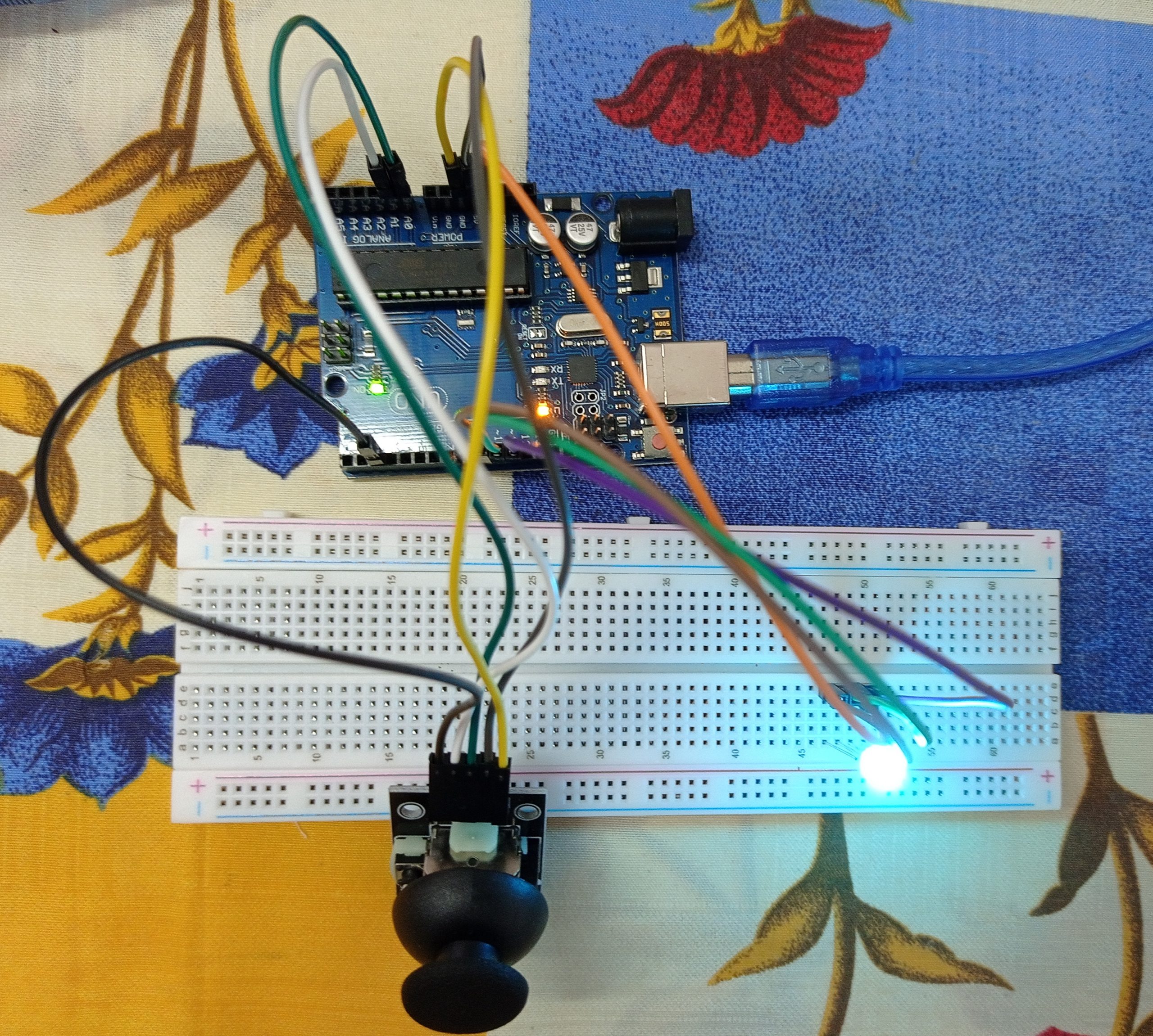
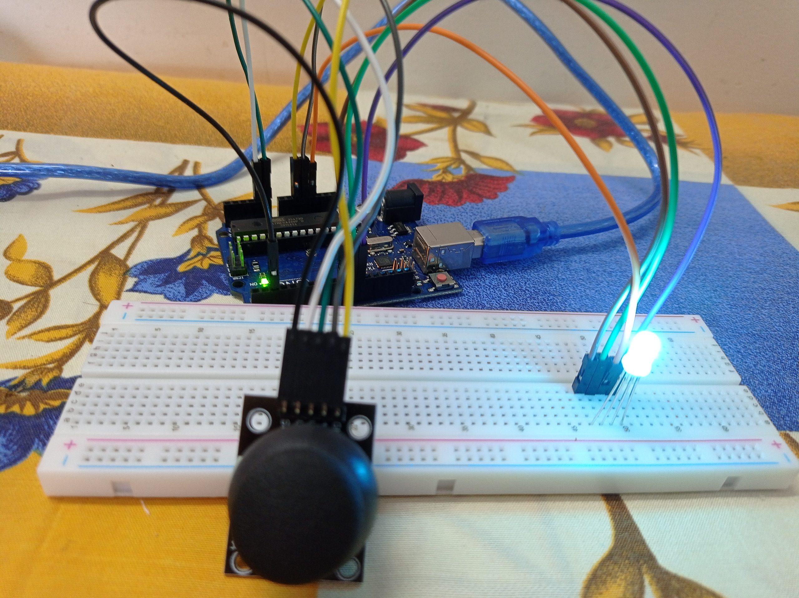
The materials that we require for this project are a breadboard, a joystick module, jumper wires, a RGB LED, and an Arduino Uno.
Forwarding towards the code, it is quite easy to understand if you have prior experience in the programming language C. Firstly, all the variables are initialized. After this, the two main methods void loop and void setup are defined.
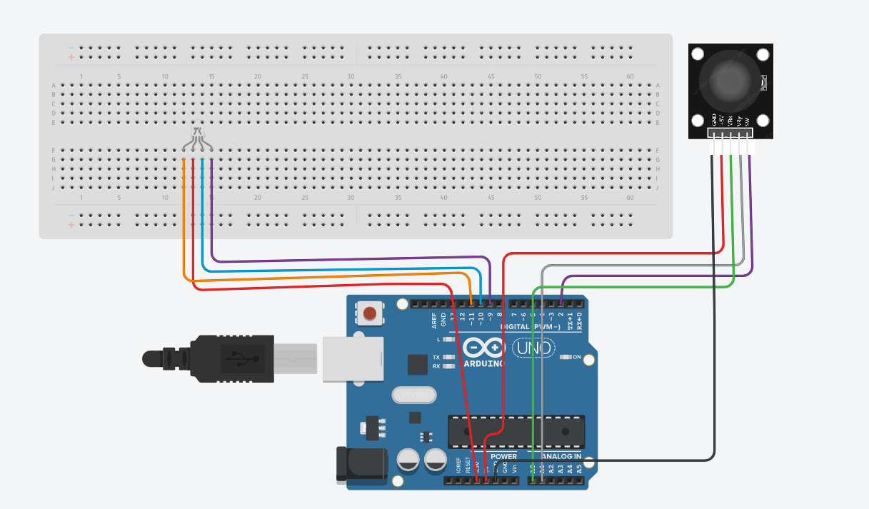
Further to the connections part, we can see that all the connections are directly done to the RGB LED and the joystick module. Here 3.3V, 5V, and ground are directly connected to the RGB LED and the joystick module. Like other connections, we don’t use negative and positive rails.
On completion of all the connections as per the circuit diagram given below, you’ll connect the Arduino board to the pc, then the code given below might be uploaded to the Arduino board using the Arduino IDE software. For newbies, please do select the proper model of the Arduino board and choose the right port under the choices within the Arduino IDE software. Finally, you can move the joystick and see the colors change on the RGB LED. Again, for the newbies out there, after uploading the code to the Arduino board you’ll just power up the Arduino board employing a power source and it’ll work.
Overview – In this undertaking, we will utilize a joystick module to change the shades of RGB LED.
Circuit
Circuit Diagram
Note
Check whether all pins are connected in proper positions.
Code
 const int PUSHBUTTON_PIN = 2;
 const int RED_PIN = 11;
 const int GREEN_PIN = 10;
 const int BLUE_PIN = 9;
 const int redX = 512;
 const int redY = 1023;
 const int greenX = 1023;
 const int greenY = 0;
 const int blueX = 0;
 const int blueY = 0;
 void setup() {
  Serial.begin(9600);
  // Set the Joystick button as an input
  pinMode(PUSHBUTTON_PIN, INPUT);
  digitalWrite(PUSHBUTTON_PIN, HIGH);
  pinMode(RED_PIN, OUTPUT);
  pinMode(GREEN_PIN, OUTPUT);
  pinMode(BLUE_PIN, OUTPUT);
 }
 void loop() {
  int xAxis = analogRead(A0);
  int yAxis = analogRead(A1);
  // Flip orientation (if needed)
  xAxis = map(xAxis, 0, 1023, 0, 1023);
  yAxis = map(yAxis, 0, 1023, 1023, 0);
  int distanceRed = sqrt(pow(abs(redX - xAxis), 2) + pow(abs(redY - yAxis), 2));
  int distanceGreen = sqrt(pow(abs(greenX - xAxis), 2) + pow(abs(greenY - yAxis), 2));
  int distanceBlue = sqrt(pow(abs(blueX - xAxis), 2) + pow(abs(blueY - yAxis), 2));
  int brightRed = 255 - constrain(map(distanceRed, 0, 1023, 0, 255), 0, 255);
  int brightGreen = 255 - constrain(map(distanceGreen, 0, 1023, 0, 255), 0, 255);
  int brightBlue = 255 - constrain(map(distanceBlue, 0, 1023, 0, 255), 0, 255);
  if (digitalRead(PUSHBUTTON_PIN) == 0) {
   brightRed = 255;
   brightGreen = 255;
   brightBlue = 255;
  }
  analogWrite(RED_PIN, brightRed);
  analogWrite(GREEN_PIN, brightGreen);
  analogWrite(BLUE_PIN, brightBlue);
  Serial.print("KEY: ");
  Serial.print(digitalRead(PUSHBUTTON_PIN));
  Serial.print(", X: ");
  Serial.print(xAxis);
  Serial.print(", Y: ");
  Serial.print(yAxis);
  Serial.print(", R: ");
  Serial.print(brightRed);
  Serial.print(", G: ");
  Serial.print(brightGreen);
  Serial.print(", B: ");
  Serial.print(brightBlue);
  Serial.println("\n");
  delay(100);
 }
