How to control LEDs with Ultrasonic Sensor on Arduino!
Ever thought of making a measurement system? Now, it’s at the reach of your hands. Thinking how will it be possible? It’s all simple with the help of Arduino. To those who are living under a rock, Arduino is a microcontroller that enhances complex circuits into simple ones. Coding an Arduino is easy as far as you know the programming language C.
Nowadays, most of them in this field are utilizing Arduino on both huge and little scale. Arduino is being used starting from high school students to even professionals for making up big projects. Now for the people who are new to this, they can purchase an Arduino starter kit which usually has all the items required for this project. Like the universe, everything in its starting stage would be confusing. Similarly, even Arduino and its connections would be tough in the beginning. I think that the below project would be a nice start for beginners.
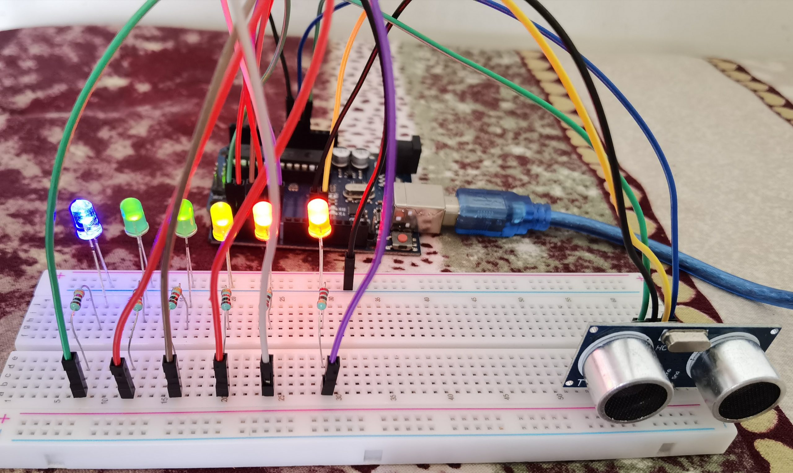
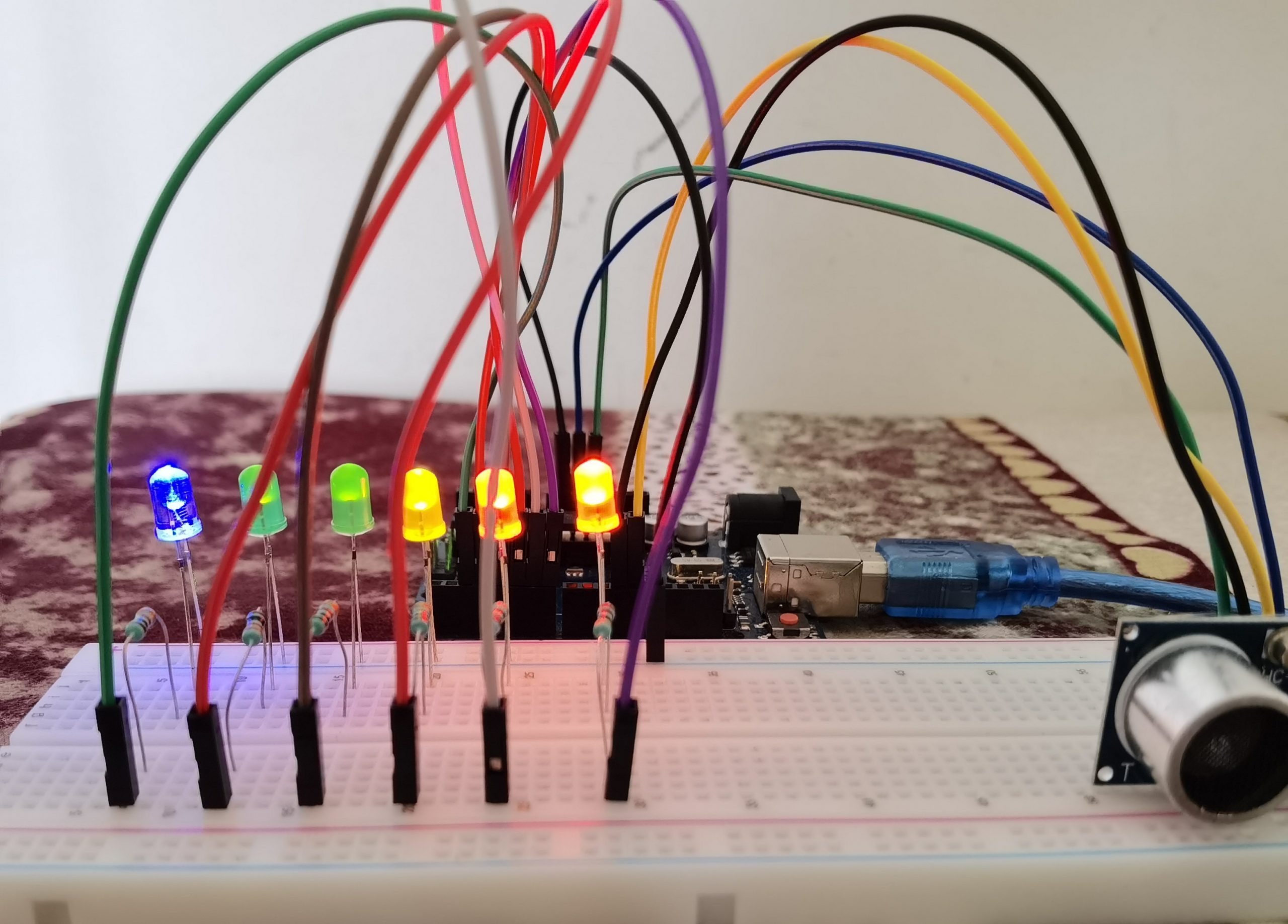
The items needed for this project are a breadboard, jumper wires, six LEDs preferably of different colors, an Arduino Uno, few resistors, and an ultrasonic sensor.
Heading towards the code, it looks quite uncomplicated. First, we initialize all the variables. Now, we set up both the main methods void setup and void loop.
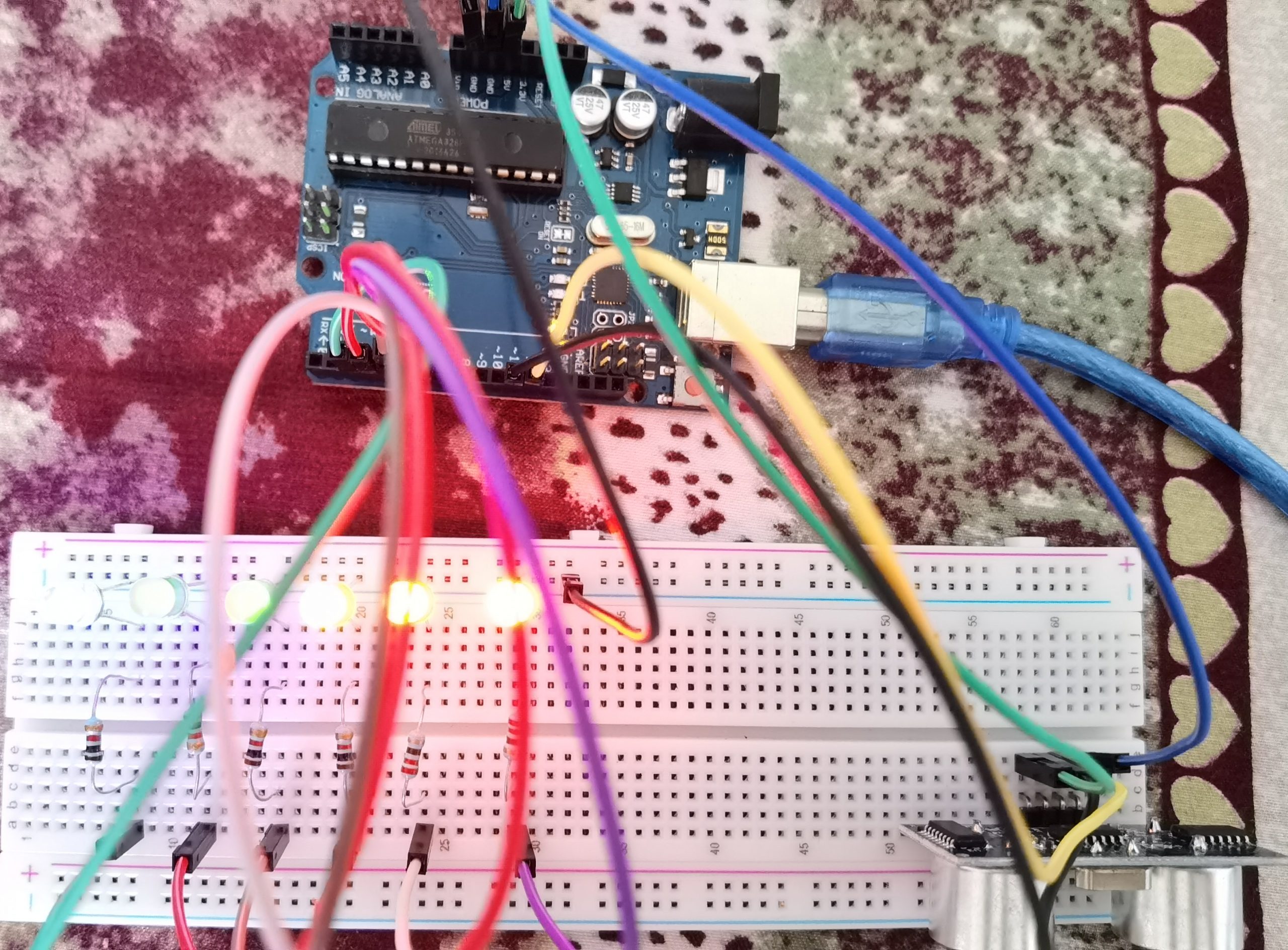
Moving on to the connections part, it looks pretty easy. One of the connections goes from the ground of the Arduino board to the negative rail of the breadboard. Other connections are done directly to the ultrasonic sensor and indirectly to LEDs via the resistors.
After setting up all the connections properly, you can plug the Arduino board into the USB port using the USB cable. Now using the Arduino IDE software you can upload the code given below. Finally, you can test your project by placing your hand or an object in front of the ultrasonic sensor at different positions and then you can see certain LEDs turning on and off. Now back to the starters, there is no need to be connected with the PC after uploading the code to the Arduino board, you can just use an electricity source like a power bank to power up the Arduino board.
Overview – In this project, we will be using an Ultrasonic Sensor to control the LEDs using distance measurements.
Circuit
Circuit Diagram
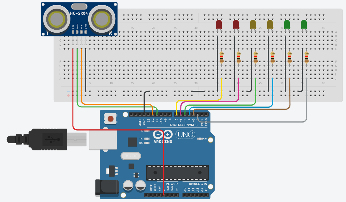
Note
1K resistors are used in this project. Also check whether all pins are connected in proper positions.
Code
 const int trig = 11;
 const int echo = 12;
 const int LED1 = 2;
 const int LED2 = 3;
 const int LED3 = 4;
 const int LED4 = 5;
 const int LED5 = 6;
 const int LED6 = 7;
 int duration = 0;
 int distance = 0;
 void setup()
 {
  pinMode(trig , OUTPUT);
  pinMode(echo , INPUT);
  pinMode(LED1 , OUTPUT);
  pinMode(LED2 , OUTPUT);
  pinMode(LED3 , OUTPUT);
  pinMode(LED4 , OUTPUT);
  pinMode(LED5 , OUTPUT);
  pinMode(LED6 , OUTPUT);
  Serial.begin(9600);
 }
 void loop()
 {
  digitalWrite(trig , HIGH);
  delayMicroseconds(1000);
  digitalWrite(trig , LOW);
  duration = pulseIn(echo , HIGH);
  distance = (duration / 2) / 28.5 ;
  Serial.println(distance);
  if ( distance <= 5 )
  {
   digitalWrite(LED1, HIGH);
  }
  else
  {
   digitalWrite(LED1, LOW);
  }
  if ( distance <= 7 )
  {
   digitalWrite(LED2, HIGH);
  }
  else
  {
   digitalWrite(LED2, LOW);
  }
  if ( distance <= 10 )
  {
   digitalWrite(LED3, HIGH);
  }
  else
  {
   digitalWrite(LED3, LOW);
  }
  if ( distance <= 15 )
  {
   digitalWrite(LED4, HIGH);
  }
  else
  {
   digitalWrite(LED4, LOW);
  }
  if ( distance <= 17 )
  {
   digitalWrite(LED5, HIGH);
  }
  else
  {
   digitalWrite(LED5, LOW);
  }
  if ( distance <= 20 )
  {
   digitalWrite(LED6, HIGH);
  }
  else
  {
   digitalWrite(LED6, LOW);
  }
 }
