How to use Photoresistor with LED and Buzzer on Arduino!
Have you ever thought of building your own security system? If yes, then it’s your time. You might think now how’s it possible even? It’s easy with the help of Arduino which can make complex circuits feel very easy. Nowadays, Arduino has been adopted by students in various fields like Information Technology and Engineering. The coding part of the Arduino is also not that complex for those who have prior experience in the C programming language.
Using the potential of Arduino several projects are being made both on a mega and small scale. Possibly, if you are new to this, then I might recommend you to buy an Arduino starter kit which usually would include possibly all the items that we require for this project. Like you guys know, everything doesn’t come by itself easily. In an identical manner, even being used to Arduino, the connections and all might be a bit hard. I hope that this prototype would really help out the ones who are new to this.
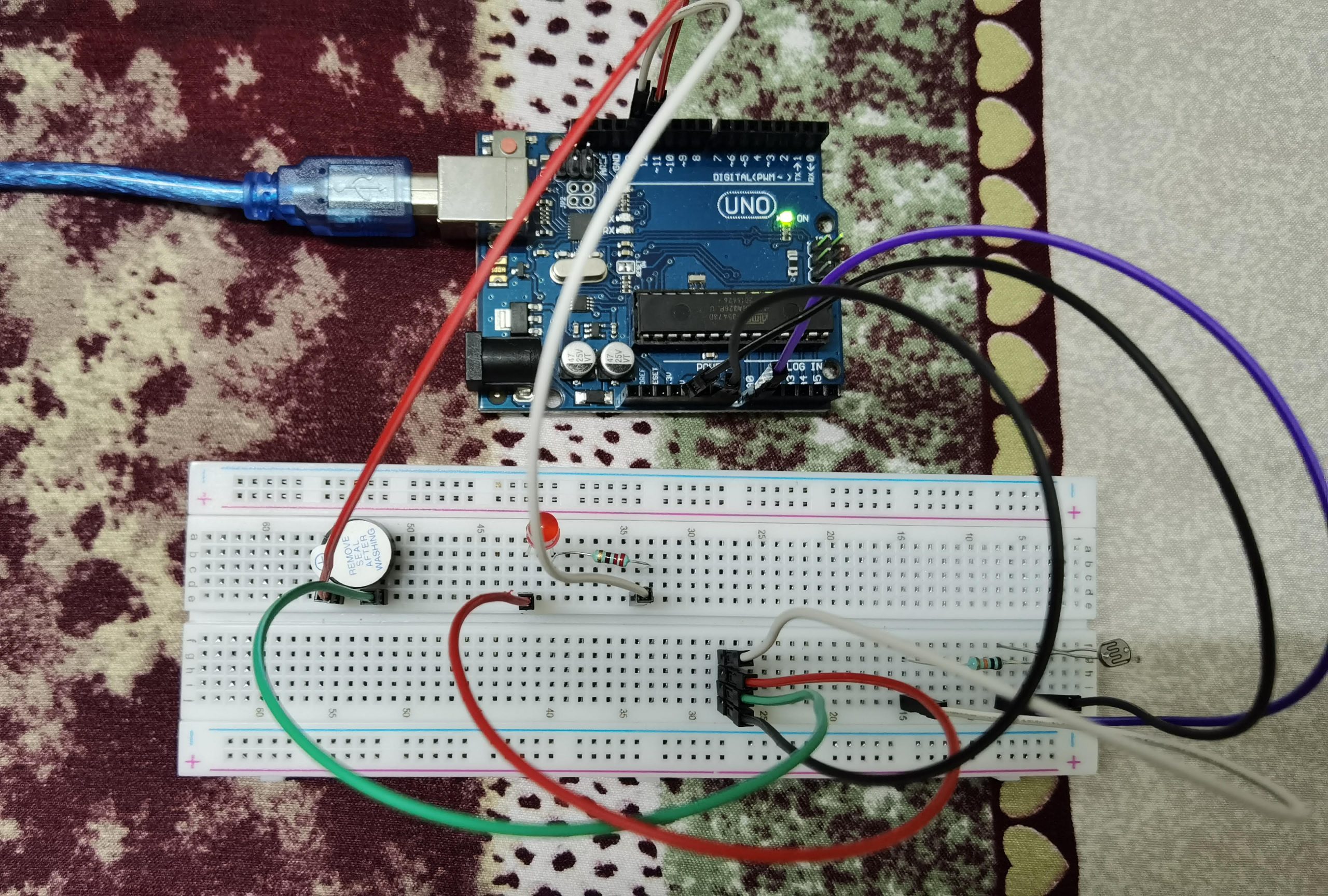
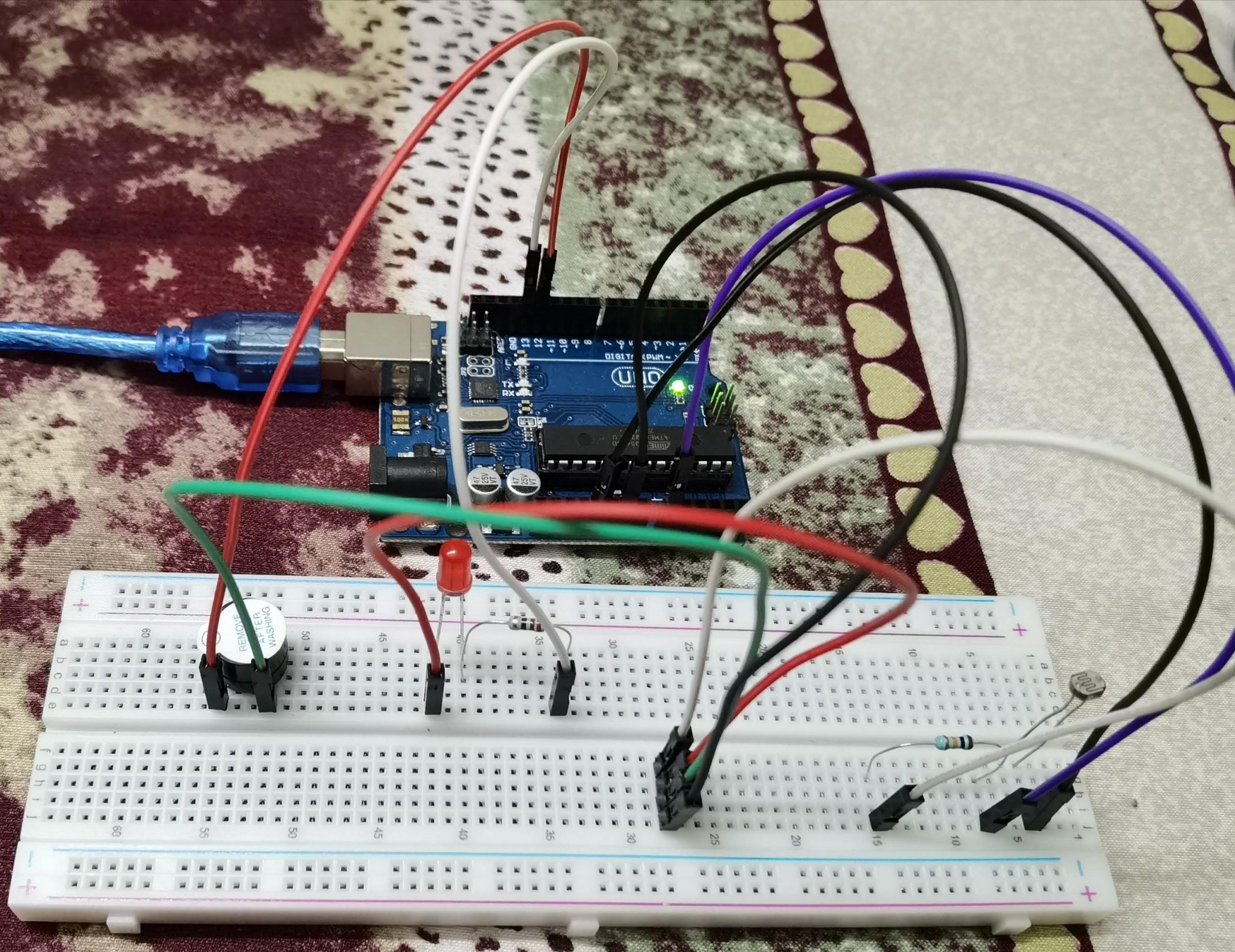
Materials required for this prototype are few resistors, jumper wires, an Arduino Uno, a LED, a photoresistor, a breadboard, and a piezo buzzer.
Going towards the code, it looks pretty straightforward. Here first we initialize all the variables. Now, I have set up two main methods void loop and void setup.
Next on to the connections, here all the connections are done directly with no use of positive and negative rails on the breadboard. Some are connected indirectly with the resistors in the middle.
Finally, after completing all the connections properly as per the below-given code, you connect the Arduino board to the USB port and then upload the code given below via the Arduino IDE software. Now, if the light is blocked from the photoresistor then the LED will start to blink, the buzzer will beep and on the Serial Monitor within the Arduino IDE it will print ‘ALARM ACTIVATED’. Again for those new to this, you can disconnect from the PC after uploading the code and use an electricity source to keep the Arduino on.
Overview – In this project, we will be using a photoresistor to detect the decrease in light and send output through LED and Buzzer.
Circuit
Circuit Diagram
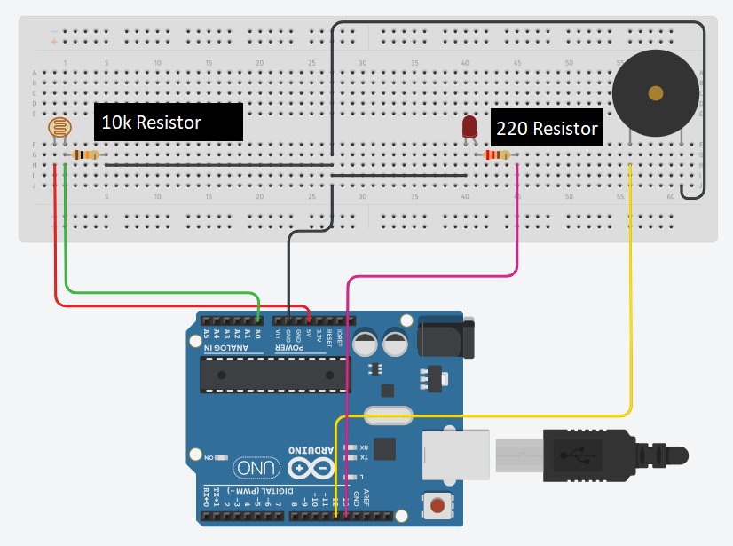
Note
10K and 220 ohm resistors are used above. We can use either active buzzer or piezo buzzer in this project. Also check whether all pins are connected in proper positions.
Code
 //set pin numbers
 const int ledPin = 13;
 const int buzzerPin = 12;
 const int ldrPin = A0;
 void setup () {
  Serial.begin(9600);
  pinMode(ledPin, OUTPUT);
  pinMode(buzzerPin, OUTPUT);
  pinMode(ldrPin, INPUT);
 }
 void loop() {
  int ldrStatus = analogRead(ldrPin); //read the state of the LDR value
  if (ldrStatus >= 400) {
   noTone(buzzerPin);
   digitalWrite(ledPin, LOW);
   Serial.println("ALARM DEACTIVATED");
  }
  else {
   tone(buzzerPin, 100);
   digitalWrite(ledPin, HIGH);
   delay(100);
   noTone(buzzerPin);
   digitalWrite(ledPin, LOW);
   delay(100);
   Serial.println("———– ALARM ACTIVATED ———–");
  }
 }
